Institutions to take box eartioning machine production line efficiency plays a decisive role.So take a reasonable design agency boxing agency boxing box packaging industry has a very important significance.Here according to the manufacture’s requirements,combined with the relevant design space bar linkage design ideas to take to achieve the linkage action space case, and the use of the reverse trajectory method the location of five institutions analyzed.
According to the connecting rod length constant conditions, the establishment of the space bar axis component equation of motion parameters. Applied Solid Words modeling, dynamic process simulation run institutes. The agency has been put into production, after a practice, demonstration, reasonable structure.
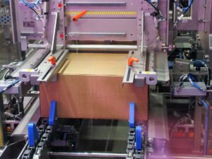
The Carton folding machine is an independent modular mechanism on the cartoning machine production line, and a top-opening and Carton folding machine is now designed. The main feature of this mechanism lies in the choice of its control method. Compared with planetary gear control, it has higher operating precision and stability. Compared with cam control, it has a wider application range and higher flexibility for series products.
iskenderun escort,
iskenderun escort,
iskenderun escort,
hatay escort,
iskenderun escort,
iskenderun escort,
iskenderun escort,
iskenderun escort,
iskenderun escort,
iskenderun escort,
iskenderun escort,
iskenderun escort,
antakya escort,
antakya escort,
bursa escort,
görükle escort,
bursa escort,
bursa escort,
hatay escort,
diyarbakır escort,
diyarbakır escort,
diyarbakır escort,
elazığ escort,
elazığ escort,
elazığ escort,
arsuz escort,
arsuz escort,
escort denizli,
escort denizli,
escort denizli,
escort denizli,
escort denizli,
escort denizli,
escort denizli,
escort denizli,
escort denizli,
escort denizli,
escort denizli,
escort denizli,
escort denizli,
escort denizli,
escort denizli,
escort denizli,
escort denizli,
escort denizli,
adana escort,
adana escort,
adana escort,
adana escort,
adana escort,
adana escort,
escort malatya,
escort malatya,
eskişehir escort,
eskişehir escort,
manisa escort,
izmit escort,
izmit escort,
izmit escort,
izmit escort,
izmit escort,
izmit escort,
izmit escort,
izmit escort,
izmit escort,
ısparta escort,
ankara escort,
ankara escort,
gaziantep escort,
gaziantep escort,
gaziantep escort,
gaziantep escort,
gaziantep escort,
gaziantep escort,
gaziantep escort,
gaziantep escort,
seks hikayeleri,
erotik hikayeleri,
erotik seks hikayeleri,
sakarya escort,
sakarya escort,
sakarya escort,
van escort,
van escort,
mersin escort,
mersin escort,
istanbul escort,
izmir escort,
izmir escort,
samsun escort,
escort konya,
escort konya,
escort konya,
escort konya,
escort konya,
erzurum escort bayan,
erzurum eskort,
escort malatya,
alanya escort,
rent a car chisinau,
Frezerie Chisinau,
masini in chirie chisinau,
Chirie Auto Chisinau,
chirie auto chisinau
chirie auto,
porno izle,
porno,
porno izle,
turk porno,
sikis izle,
porna,
xhamster,
rus porno,
anal porno,
porno seyret,
türk porno,
amatör porno,
liseli porno,
hd porno,
sarışın porno,
mobil porno,
xnxx porno,
Eskişehir escort,
izmir escort,
erzurum escort,
erzurum escort,
iskenderun escort,
iskenderun escort,
iskenderun escort,
escort denizli,
escort denizli,
escort denizli,
escort denizli,
antalya escort,
escort denizli,
escort denizli bayan,
Cosmetologie Chisinau,
Epilare cu laser Chisinau,
Epilare laser,
Epilare cu laser,
Лазерная эпиляция,
Cosmetologie,
Прокат автомобилей,
rent a car chisinau,
Chirie auto moldova chisinau,
Прокат автомобилей в аэропорту Кишинева,
chirie auto chisinau aeroport,
Arenda Maşina chisinau
Chirie auto chisinau,
Aeroport Chirie Auto,
Chirie Auto Chisinau,
Chirie Auto Chisinau,
Лазерная эпиляция в Кишиневе,
Chirie Auto chisinau,
arenda Auto Chisinau,
1. The Basic Design Idea of the Carton Folding Machine
The box taking mechanism of the cartoning machine adopts the space link mechanism to take the box, which is composed of three actions: suction box, box delivery, and box release. The whole process is realized by compound control through the rotation of the main shaft and the swing of the space crank rocker ; The key to realize the design of this mechanism is to determine the spatial position of the box action, determine the swing amplitude of the main shaft and the swing amplitude of the space crank rocker, and determine the mutual motion coordination relationship between the two and the time difference relationship of each movement.
The determination of the pose and its installation location is also a key issue in this design. According to the requirements of the production line, the motion trajectory ¨1 required by the mechanism is realized by using the trajectory reverse method. This trajectory is the reciprocating motion of AB—C—B—A, as shown in Figure 1. According to the characteristics of the motion track, the mechanism is comprehensively analyzed and designed.
2. Location Analysis of Space Mechanism
Determination of the degree of freedom of the spatial link mechanism
First of all, according to the qualitative analysis of this mechanism, the realization of the whole movement process needs to be controlled by the compound swing of two pendulum shafts, that is, this mechanism,the degree of freedom is 2; in addition, according to the analysis and calculation of the degree of freedom of the mechanical design principle, the result is also a mechanism with 2 degrees of freedom.
Structural analysis of space link mechanism
The starting position of the self-suction box is the active reciprocating rotation pendulum axis (main pendulum axis) to control the space pose of the swing arm to be consistent with the placement pose of the delivery box (as shown in the position of the suction box in Figure), while the space pose of the crank rocker is is the support limit position of the strut. At this time, with the swing of the main pendulum axis, the crank rocker starts to pull inward from the limit position of the strut support. At this time, the space crank rocker drives the strut to swing to the pull-in limit position. At this point, the space crank rocker pull-in action is completed. After that, only the main pendulum shaft continues to swing at a small angle to the position (as shown in the position of the suction box in Figure), to send the box to the desired position, and the feeding action of taking the box is completed. With the main swing shaft swinging at a small angle, the cross connection between the strut and the space crank rocker will follow the spherical swing of the active swing arm; the main swing shaft Swing back, the process is opposite to that of coming , to the position of the suction box, at this point the entire suction box action is completed.
The space Cartesian coordinate system OXYZ is established with the contact point of the active reciprocating swing shaft and the active swing arm as the coordinate origin, parallel to the mounting plate surface is the XOZ plane, the X direction is the horizontal direction, and the Z direction is the vertical direction, perpendicular to the mounting plate Facing outward is the direction of]; according to the actual requirements of the project, the movement of the spatial linkage mechanism is decomposed into two parts, that is, the movement on the plane XOZ and the plane YOZ, and the spatial linkage mechanism at this time can also be transferred to a single plane Analyze the planar mechanism; on the plane XOZ, the active reciprocating pendulum axis rotates at a certain angle.
| Component |
Description |
Function in Mechanism |
| Link |
Individual rigid bodies connected by joints. |
Transmits motion and force between connected components. |
| Joint |
Points where two or more links are connected, allowing relative motion. |
Provides controlled movement between links, dictating the type of motion (rotary, sliding, etc.). |
| Actuator |
Elements that drive the mechanism, such as motors or hydraulic/pneumatic cylinders. |
Provides the necessary motion input to the mechanism. |
| Constraints |
Factors that limit or guide the movement of the mechanism. |
Ensures the mechanism operates within desired parameters and prevents unwanted movements. |
| Degrees of Freedom (DoF) |
The number of independent movements the mechanism can make. |
Determines the flexibility and range of motion of the mechanism. |
| Kinematic Chain |
A sequence of links and joints that form a loop. |
Defines the path and manner in which motion is transferred through the mechanism. |
| Transmission Angle |
The angle at which force is transmitted between links. |
Affects the efficiency and effectiveness of force transfer in the mechanism. |
| Base or Frame |
The stationary reference link to which other links are connected. |
Provides stability and a reference point for the mechanism’s movement. |
According to the spatial relationship between the placement position of the box and the arrival position of the box, first determine the size M of the active swing arm and the guide of the suction box. The respective dimensions of the rod and the driven swing arm; on the YOZ surface, it is realized by the swing of the crank rocker ; to realize the push-pull action of the strut, it is only necessary to find out the movement track of the strut, that is, the distance between the strut and the active swing arm.
The trajectory of the connecting point, and then analyze the connecting point position of the strut, in the space coordinate system OXYZ, randomly select a point of length a on the active swing arm (close to the coordinate origin 0, the smaller the distance, the more conducive to reducing the stroke of the strut, However, it should be based on the fact that the mechanism cannot interfere). Since the active swing arm swings, its trajectory should be a section of spherical arc with 0 as the center and a as the radius. It must be swung from the YOZ plane to the XOZ plane. During the process, the length of the rod remains unchanged .
To ensure that the position of the strut meets the requirements, the distance from the position of the connection point to the active swing arm should also be a. Realization; to realize the push-pull action of the strut, it is only necessary to find out the trajectory of the strut, that is, the trajectory of the connection point between the strut and the active swing arm, and then analyze the position of the connection point of the strut, and choose any in the space coordinate system OXYZ A point with a length of a on the active swing arm (closer to the coordinate origin 0, the smaller the distance is, the more favorable it is to reduce the stroke of the strut, but it should be based on the fact that the mechanism cannot interfere ).
Since the active swing arm swings, its The trajectory should be a segmented spherical arc with 0 as the center and a as the radius. It should be placed from the YOZ surface to the XOZ surface. According to the rule that the length of the pole does not change during the movement, the position of the pole should be the connection point to ensure that it meets the requirements.
When the suction box is in position (as shown in Figure 3), the angle between the position of the suction box guide rod and the horizontal plane is p, and the coordinates of the connection point should be A(asin0, acos0,a); At this time, the strut is fully propped up, and the crank rocker is pushed to the limit position. The suction box is delivered to the box, and the box should be released during the process of sending the box to the box
Avoid the interference between the guide rod of the suction box and the mechanism of the box to be placed, so it should have reached the XOZ surface before reaching the position of the box during the box feeding process, such as Figure shows the position and posture when the box delivery process has just reached the XOZ plane. At this time , only the main swing shaft drives the active swing arm to continue to swing, while the crank rocker stops swinging. The rocker is pulled to the limit position, but the strut will follow-up rotation is performed under a fixed spherical hinge; at this time, the box only moves upward on the XOZ surface, and the angle between the position of the active swing arm and the XOY surface is y, and the main pendulum axis has rotated over Ot degrees.The rotation angle of the main axis in a box picking process is Ol+y.
According to the coordinates of the connection point at the extreme positions of the two actions, H2= a2(sin0-cosy)2+a2(cos0-siny)2+4a2; the arc distance between the two points can be obtained, that is, the distance of the pole in the whole process The push-pull stroke £ can also calculate the swing angle of the active swing arm at this time.
When the swing arm swings well enough to be parallel to the XOZ plane, the crank rocker swings to the pull-back limit position. At this time, the strut starts to swing with the spherical hinge as the center of the ball: until it reaches the position where the box is to be placed; according to this, the crank can be judged The hinge position of the pull-back limit position of the rocker should be on the perpendicular bisector of the swing range of the active swing arm on the YOZ plane. During the whole box feeding process, the time period for the simultaneous movement of the main swing shaft and the crank rocker is when the space connecting rod moves from the suction box to the XOZ plane position. The swing range of the active swing arm during this period is the active swing arm and the support rod.
The swing range of the connecting point is the arc distance £ drawn from point Y to point A , and the movement trajectory of the connecting point during this period, surface with the origin of the coordinates as the center a and the spherical surface with the distance from point B to point A as the diameter and the spherical surface with the coordinates of the midpoint c as the center of the sphere. It can be calculated that this surface is perpendicular to the XOY surface, and the included angle with the XOZ surface is or. It can also be known that the strut performs push-pull action in the surface ABC, that is, the crank rocker swings in the surface ABC; according to the engineering design requirements, the crank can be The swing angle of the rocker is tO, and the length of the rocker can be converted to z=a li from the arc swing characteristic of the rocker with the stroke of £i; when the initial position of the crank rocker is at the suction box position, In a straight-line posture with the crank, the swing angle of the crank rocker can be set to 90°. Or any other angle (depending on the push-pull range), set the installation position of the crank and rocker according to the operating space, and correspondingly obtain the length of the corresponding strut . o 7.8| can be fully determined; only part of the relevant data of this mechanism is provided here : the inclination of the initial pose of the box is 30. , y is 15. The swing angle ∞ of the crank rocker is 90°, and the angle between rod 4 and rod 5 is always greater than 90°.
Conclusion
The Carton folding machine has been put into production in a certain company. According to the actual operation results, it is concluded that the designed space linkage mechanism and its control mechanism do not interfere with each other, and the structure is reasonable. In order to realize the high-speed and repeated positioning of the production line of the top-opening box-taking pharmaceutical packaging machinery Precision provides a good guarantee.
