With the rapid development of production technology in our country, people have higher and higher requirements for the performance of machined T. On some assembly line production equipment or processing equipment for batch products. Some processing parameters need to be modified or the operation of equipment needs to be monitored, such as: carton cutting equipment, and the cutting accuracy and yield need to be monitored in real time.
This paper takes the rotary die cutting machine as an example, and introduces a control system with PLC as the core. It uses touch screen input and servo motor output to control the speed of the die cutting machine knife roller, which improves the die cutting accuracy and reduces the scrap rate. Therefore, it can well meet the needs of the modern printing industry for carton die cutting, and because of the introduction of the control system, the portability of the die cutting machine has been enhanced, and it can be used alone or in combination.
1. The Movement of the Rotary Die Cutting Machine
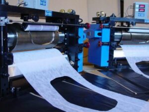
The die cutting plate table and the working part of the pressure-cutting mechanism (pressure roller ) of the rotary die cutting machine (as shown in Figure 1) are all cylindrical. The rubber roller and the knife roller are in contact with each other for a long time during the die cutting process, and the outermost layer of the rubber roller is a layer of resin material rubber. The cutter on the knife roller acts on the rubber for a long time, causing local damage and deformation of the rubber. This will cause the diameter of the rubber roller to change gradually, so that the linear speed of the rubber roller will also change accordingly, resulting in inconsistent linear speeds of the knife roller and the rubber roller. In this way, the cardboard passing between the two during the die cutting process will be deformed or even damaged, resulting in waste products.
2. Die Cutting Machine Control System Scheme
In this design, the function to be realized by the control system of the die cutting machine is: when the rubber part of the rubber roller is deformed. Use a cutter to remove the rubber of the deformed part. After turning, measure the diameter of the rubber roller again. Then adjust the rotation speed of the rubber roller shaft according to the diameter , so that the linear speed of the rubber roller and the knife roller after turning are still consistent , thereby avoiding the generation of waste products.
The general plan of the control system: use the industrial touch screen to transmit the measured diameter of the rubber roller to the PLC through programming—PLc controls the pulse output module to output the corresponding pulse signal through the programmed program—the control pulse signal passes through the feeding amplifier— And then control the rotation speed of the feeding motor. The control system hardware mainly includes the following five parts: display module, PLC main control module, positioning module, servo system and encoder.
3. Display Module
The touch screen selected in this design is the MTS06S type in the eView500 series touch screen man-machine interface. eView500 series touch screen human-machine interface is a series of human-machine interface products that are constantly improving with the development of embedded system technology. It has a high-performance embedded hardware platform, is equipped with a powerful and easy-to-use configuration software EasyBuilderS00, and provides a complete connection scheme with various controllers. With excellent performance-price ratio and stable and reliable quality, it can rapidly improve the working efficiency of the control system .
4. PLC Main Control Module
The PLC programmable controller is the core part of this control system. The function to be realized by this program is: read the data of the diameter of the rubber roller transmitted from the touch screen, and detect the rotation speed of the cutter roller, and according to the diameter of the rubber roller and the diameter of the cutter roller And the detected three data of the rotation speed of the knife roller output a pulse with a certain frequency. Make the rotation speed of the servo motor controlled by the output pulse frequency equal to the rotation speed of the knife roller.
Programming of PLC program: The main content of the program is to use PLC to detect the rotation speed of the knife roller, calculate the four floating points of data, and output high-speed pulses.
For the detection of the rotation speed of the knife roller, an encoder can be used to detect the pulse frequency when the knife roller is moving. And because the rotation speed of the knife roller is very high, the pulse frequency is also very high, so the high-speed counter function of the FX2N series single-chip microcomputer is used.
The four arithmetic operation part of the data needs to use the four arithmetic operation instructions in the PLC. Divide the obtained pulse frequency by the number of lines of the encoder to obtain the rotation speed of the cutter roller. It is thought that the encoder with 2000 lines is used in this design, so the rotation speed of the cutter roller is D0/2000 (r/s) , and store the data in the data memory of the PLC for subsequent calculation.
The function and action it realizes is, when X02 is ON, divide the value of the product stored in D2030 by the diameter of the rubber roller, and the touch screen transmits the data of the diameter of the rubber roller to the PLC, which is stored in the PLC D2000 unit of the data storage unit. The result after the operation is stored in the D2040 unit in the data memory. After the rotation speed of the rubber roller is obtained, according to the speed reduction ratio between the feeding motor controlling the rotation speed of the rubber roller and the speed change system between the rubber roller, the required rotation speed of the feeding motor can be obtained. The function and action it realizes is, when X02 is ON, the data in D2040 in the data storage unit is multiplied by a constant 18, and the calculated result is stored in D2050 unit, and its unit is r/min.
High-speed pulse output In this design, the high-speed pulse output is selected from the FX2N-IOPG pulse output module. The use of this module mainly involves the functions and setting methods of various parameters of the module . Write pulse speed, write feed speed, write parameter, write maximum speed, write base speed, write running speed, error reset, stop running command, forward pulse stop command. So far , the content of the main program of the programmable controller is generally determined, and then a series of auxiliary functions such as start, stop, emergency stop and other functions are considered comprehensively, and the program of the entire control system is compiled. Considering that this design is an actual project for the manufacturer, which involves factors such as the confidentiality of the manufacturer’s technical data, only the main program that needs to be compiled for the functions to be realized by the above-mentioned control system is listed.
| Feature/Component |
Description |
Importance/Impact for Die Cutting |
| Processor |
The brain of the PLC that interprets and executes the control logic. |
Ensures efficient and accurate execution of cutting processes. |
| Memory |
Stores the control program, set parameters, and data logs. |
Allows for consistent operation and historical data retrieval. |
| Input/Output (I/O) System |
Interfaces with sensors (inputs) like material presence detectors, and actuators (outputs) such as cutting blades. |
Enables the PLC to make real-time decisions based on input data and actuate machinery accordingly. |
| Communication Ports |
Allows the PLC to communicate with external devices like HMIs, computers, or other networked systems. |
Enables operators to program, monitor, and diagnose the machine remotely. |
| Scan Cycle |
Represents the time PLC takes to read inputs, process the logic, and update the outputs. |
Determines the machine’s responsiveness to changes or errors in the process. |
| Safety Protocols |
Pre-programmed routines or checks that ensure safe operation. |
Helps in preventing accidents or damage to the machine, especially during malfunctions. |
| Fault Handling & Diagnostics |
Identifies, processes, and displays system errors or anomalies. |
Allows operators to quickly address issues and minimize downtime. |
| Programming Interface |
Software or platform used to program the PLC’s operations and sequences. |
Determines ease of updating or modifying machine behavior. |
| Special Modules |
Additional PLC modules that offer specialized functionalities (e.g., high-speed counting, advanced motion control). |
Expands the capabilities and precision of the die cutting machine. |
| Backup & Recovery |
Features that allow for saving and restoring operational settings and programs. |
Ensures minimal disruption in case of failures or changes, allowing quick recovery. |
5. Positioning Module
The positioning module selected in this design is FX, a 10P (; pulse output module, which is a module that outputs a maximum of 1MHz pulse train and drives a single-axis stepper motor and servo motor. The positioning module is more functional and positioned than FX, One 1PG is greatly improved, so choose this positioning module as the pulse output unit of the control system in this design.
Conclusion
The design adopts the design concept of mechatronics. Use industrial touch screen and programmable controller to transform the die cutting machine to realize the human-computer interaction function, make the die cutting machine easy to use, and provide theoretical support for the communication interface design; analyze the cause of the measurement error of the electric field encoder, Program portability; though, it can be used as a reference for electric field encoder design.
